4 Bit Full Adder Circuit Diagram
Cs3410 fall 2015 lab 0 10+ adder circuit diagram 4 bit adder subtractor circuit diagram
4 Bit Adder Subtractor Circuit Diagram - Wiring Scan
4 bit adder subtractor circuit diagram 4 bit adder circuit diagram caret x digital Full adder logic diagram and truth table
Circuit adder bit diagram logic computing learn let
Adder bit circuitverse4 bit adder circuit diagram Adder quantum binary ibm qiskitLet's learn computing: 4 bit adder circuit.
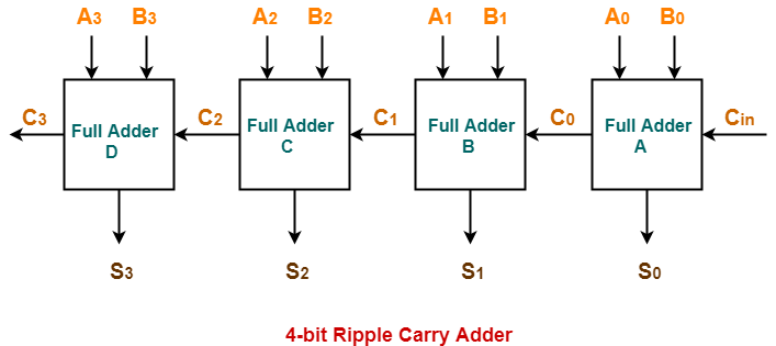
Verilog for beginners: 4-bit carry ripple adder20+ full adder block diagram Adder parallel truthCs 3410 spring 2018 lab 1.

Adder bit description introduction hardware language ppt powerpoint presentation half gate slideserve level
Adder bit logisim using circuit ripple carry build help ta sub ask create re4 bit full adder circuit, truth table and symbol. implement 4 bit Adder half addersAdder bit parallel four circuit binary diagram block example detailed discussion.
4 bit full adder circuit diagramFull-adder circuit, the schematic diagram and how it works – deeptronic Full adder circuit: theory, truth table & constructionFull adder circuit and its construction.

Chinmay oli
3 bit full adderAdder circuit diagram geeksforgeeks bit subtractor binary source [diagram] 8 bit adder circuit diagram4 bit adder circuit diagram.
Adder adders libretexts circuits pageindexAdder circuit diagram carry using truth table construction 4bit schematic shown ttl chip ahead feature below look 😊 four bit parallel adder. 4 bit binary adder circuit / block diagramLet's learn computing: 4 bit adder/subtractor circuit.

Adder bit ripple carry verilog four block adders cascading diagram beginners figure formed
Digital logicAdder subtractor bit circuit add sub overflow complement logic detection carry designing control addition digital line questions zero computer define Adder bit circuit subtractor ripple carry diagram logic using project only digital computing learn let its build indie electronicsAdder circuit diagram schematic bit works figure.
Logic gatesGiven a 4-bit full-adder-based alu (see diagram), Cd4008 4-bit full adder ic pinout, working, example and datasheetAdder bit circuitverse.

Adder gate adders implement expressions
4 bit parallel adder circuit diagram4-bit adder and subtractor circuit explained 6.4: 2-bit adder circuitAdder subtractor circuit.
Adder bit circuit logic half make gates diagram comparator two electronics first questions cout difference between there simple second puzzleAdder circuit diagram Adder bit using circuit adders half four implementation watson circuits just box latech edu.

4 Bit Parallel Adder Circuit Diagram - IOT Wiring Diagram

CS3410 Fall 2015 Lab 0

😊 Four bit parallel adder. 4 bit Binary adder circuit / block diagram

4-bit Adder and Subtractor Circuit Explained - YouTube

4 Bit Full Adder Circuit Diagram

CircuitVerse - 4 bit binary adder

Full Adder Circuit: Theory, Truth Table & Construction